Repair of a Marine Digital Ammeter
I found a marine-rated digital ammeter at a thrift store, but when I got home I was disappointed to find it wasn’t working. In this article I’ll show how I found the problem and repaired it.
Safety First
This article is presented for informational purposes only. Dismantling and handling electronic devices can be dangerous. Never dismantle or handle a mains-powered circuit while it is connected to power. Components of circuits, even ones with low input voltage (such as disposable camera flashes) can generate hazardous voltages during operation. Capacitors can store large amounts of energy at hazardous voltage even after input power to a circuit is removed, and discharging them manually can generate burns or sparks.
Issue Investigation
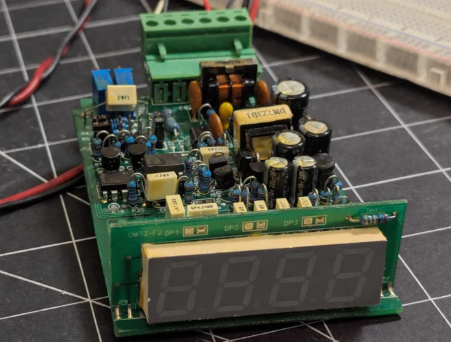
The meter is a DM-730E4A by a company called Chitai Electronic Corp, made in Taiwan. It converts a 0-50mV signal obtained from a shunt resistor into a current measurement from 0-250A. I powered on the device at its rated voltage of 24V to find it consumed about 30mA, but the LED display didn’t light up.
Circuit Analysis
The first step of the repair is to analyse the circuit to get a rough idea of how it works. No schematics or any other details about this product are available online. Some reverse engineering is needed to find out how the circuit works in order to begin diagnosing it.
I like to web search the part numbers of all the visible integrated circuits on the board and look for datasheets. Datasheets tell us important info about the parts such as their purpose, what different pins do, and important ratings such as operating voltages and currents, signal thresholds, etc. Good datasheets also contain detailed feature descriptions and example application circuits. Here are the datasheets of the two most prominent chips on the board:
I examined some of the traces and connections around the power converter and could then draw a simplified circuit diagram, shown below.
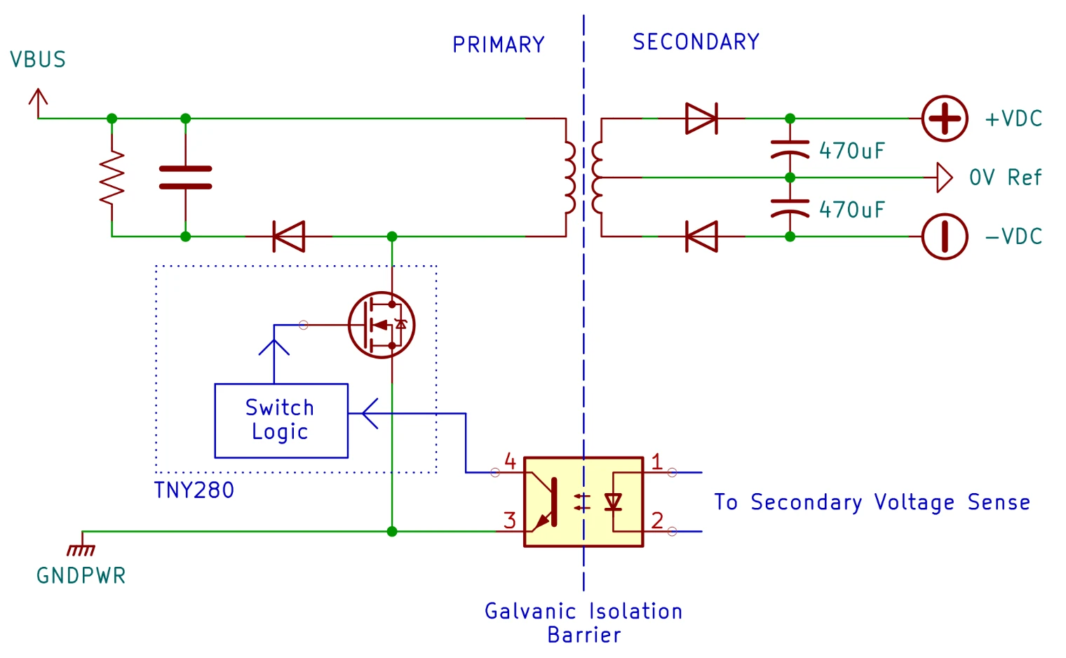
The TNY280 controls an isolated flyback converter, which changes an input voltage on one side of a transformer into a isolated, variable voltage on the other. The secondary side of the transformer has two half-bridge rectifiers each about a centre tap. The centre tap acts as the 0V reference on the secondary side, and the two half-bridge rectifiers produce a positive and negative DC voltage relative to the 0V reference. The positive and negative voltages are then passed to linear regulators, before continuing on to power the rest of the circuit.
The second major component of the circuit, AME7107R is an all-in-one chip that integrates an analog-to-digital converter and a seven-segment LED driver. According to the datasheet, it operates with a split-supply of 6V, 0V and -6V. The voltage created by the flyback converter should be at least this amount.
Taking Measurements
I first ensured that the input voltage actually made it to the first converter stage by using my multimeter to verify the 24V input voltage was present at different points along the board leading up to the transformer.
I then measured the secondary side voltages relative to the 0V centre tap point. The positive voltage was only about 1V, while the negative voltage measured -9V. The low positive voltage was probably preventing the rest of the circuit from working properly.
I soldered a wire to the 0V point on the secondary side, and hooked my oscilloscope ground to it. I scoped the positive and negative voltages just past the rectifying diode at the anode of the 470uF smoothing capacitors. If the circuit was operating correctly, I would expect to see a fairly constant DC voltage, with a repeating pattern on top of it containing regular blips of voltage followed by longer periods where the voltage drops slightly.
To understand why this pattern would exist, imagine two buckets - one small and one large. The large one has a hole drilled in the bottom, so it constantly leaks a bit. The circuit begins by filling a small bucket with water from a tap. Then, it dumps the small bucketful of water into the large one. It repeats this process until the large bucket is full. As the water drains out of the hole in the large bucket, the circuit will occasionally top off the large water bucket by dumping another small bucket of water in. The water level represents the voltage, and the flow out of the hole represents the power consumption of the rest of the circuit.
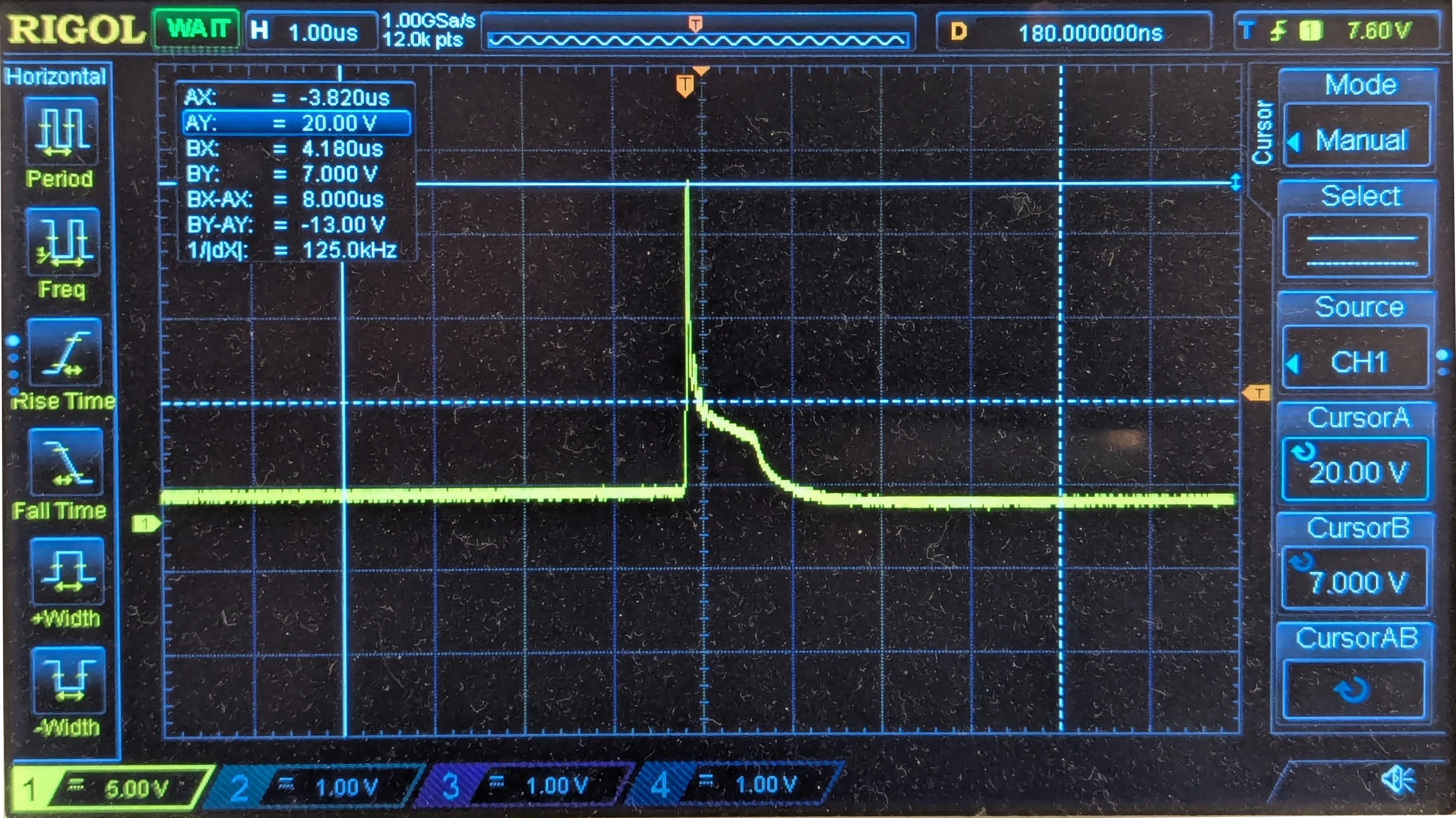
What I observed on the meter was instead that the positive rail displayed a short spike followed by a fast decay to a low voltage.
To me, this indicated that the energy from the transformer was very quickly filling the capacitor but only a small amount of energy was actually stored. It was like the large bucket had become tiny, and all the bucketfuls dumped into it mostly spilled out.
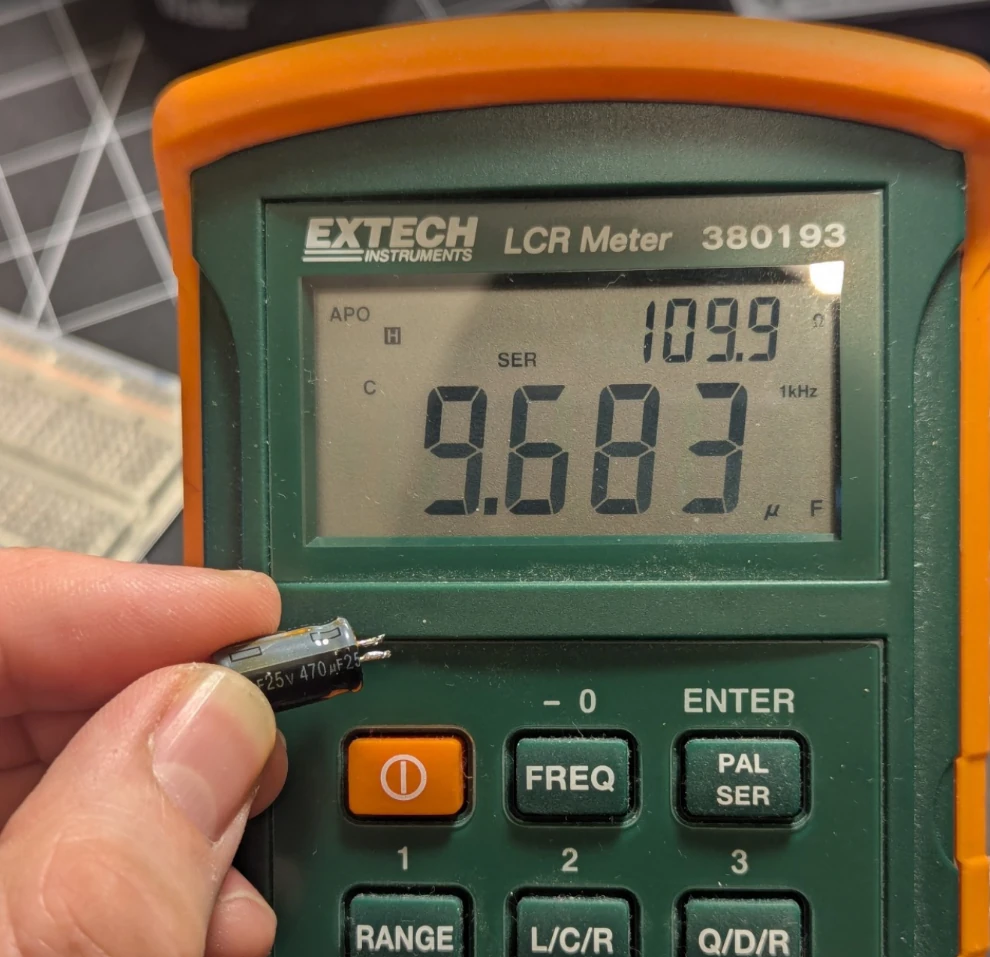
It seemed that this 13 year old electrolytic capacitor had lost much of its capacitance. I made a note of the position and polarity of all the electrolytic capacitors on the board, then desoldered them.
With the capacitors desoldered, I tested them with an LCR meter. The 470uF rated capacitor probed earlier measured only 8-10uF and >100 ohms of equivalent series resistance (ESR). Yes, that’s a 50x reduction in capacitance, and about 1000x times the ESR of a new equivalent part.
This is not a surprising result, and in fact it was the first thing I suspected when I looked at this old circuit. The quality of the electrolyte in the capacitor directly affects the capacitance and ESR, and the electrolyte quality degrades over time and especially when exposed to heat. When the capacitance drops out of spec, critical functions of the circuit stop working properly.
Repairing the Unit
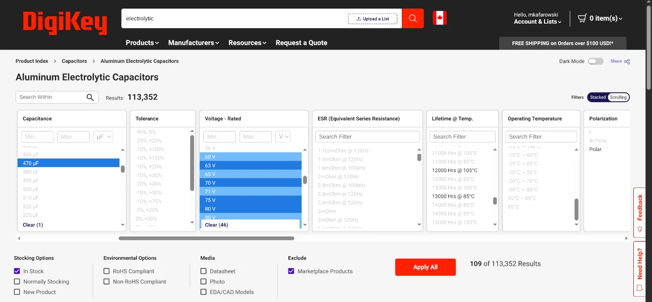
Near exact drop-in replacements were available on Digikey. I searched for new electrolytic capacitors with the following criteria:
- Match original capacitance ratings
- Match or exceed the maximum voltage rating
- Ensure fitment by filtering by the same diameter (or smaller) while maintaining a max height that would fit in the enclosure
- AEC-Q200 automotive qualification
Parts certified for automotive use are a bit more expensive but are often rated for longer lifetimes at higher temperatures.
Once the parts arrived I soldered the new capacitors to the board. When installing electrolytic capacitors one must be careful to install them with the correct polarity, otherwise they will explode when the circuit is powered on!
After the capacitors were replaced, the meter worked right away! I measured the positive and negative rails again and found that the waveform now resembled the pattern I had expected, short pulses where the converter “tops-off” the voltage, followed by longer periods where the voltage drops a bit as energy is consumed by the load.

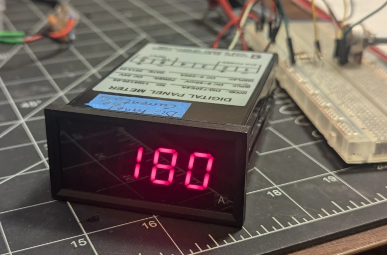
I used a simple voltage divider and a potentiometer to generate a 0-50mV signal to calibrate the meter. As I turned the potentiometer, I observed the meter changing from 0-250, its full range. Mission success!
Lifetimes of Electrolytic Capacitors
The root cause of the failure in the meter was an end-of-life wear-out failure of the electrolytic capacitors on the board.
Electrolytic capacitors work by layering a metal-oxide anode layer with a liquid/solid electrolyte cathode layer. The oxide on the anode layer serves as the dielectric (energy storage media). The oxide dielectric is very thin, and is also “roughened up” to increase its surface area. An electrolyte is used for the cathode because they can fill in the nooks and crannies of the oxide’s rough surface. The combination of a very thin dielectric and a very large surface area gives electrolytic capacitors outstandingly high capacitance for their size.
A major trade-off is that over time and through exposure to high temperature the electrolyte cathode dries out, degrading the performance. The original capacitors on the meter were rated for 105 degrees Celsius, and usually this rating is tied to a lifetime - typically 2000 hours. That’s less than three months of continuous use at the rated temperature, but for every 10 degrees of temperature reduction, lifetime roughly doubles.
If this meter came out of a boat somewhere near the equator, an ambient temperature of 30-40 degrees could be expected indoors while the boat sits out in the sun. Operating inside an enclosed box and inside an enclosed power panel, combined with self-heating through voltage ripple could result in operating temperatures exceeding 50-60 degrees. No more than 8-12 years of life can be expected in these conditions if the panel meters are in use 24/7.
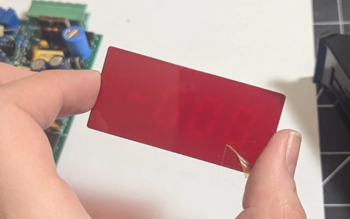
I don’t know exactly how long this meter was powered up, but the date code indicated the unit was from 2013. Also, if it’s any indication (no pun intended), the LEDs had run for long enough to discolor the tinted cover plate around certain digit segments. Neat!
You can learn more about capacitors and their lifetime characteristics in this paper by Dr. Arne Albertson.
Conclusion
Old devices that appear broken can sometimes be restored by replacing electrolytic capacitors that have degraded over time and use. These capacitors are in nearly all types of devices and have limited lifetimes especially when exposed to high operating temperature. When performing such repairs it can be fun to reverse-engineer an unknown board, and it’s a great opportunity to learn about new chips and circuits by researching datasheets and inspecting the circuit board.