EMRSNxEOS Theater Lighting Control System
(2020 - 2022) | 1527 words (6 mins)
As theatrical lighting technology has evolved, the freedom and complexity of lighting designs achievable has become nearly limitless. Articulated mirrors steer light around a stage. Electromechanical filters change a beam’s characteristics. High power RGB LED fixtures can create millions of colors. The number of unique controls for each show setup can reach into the thousands.
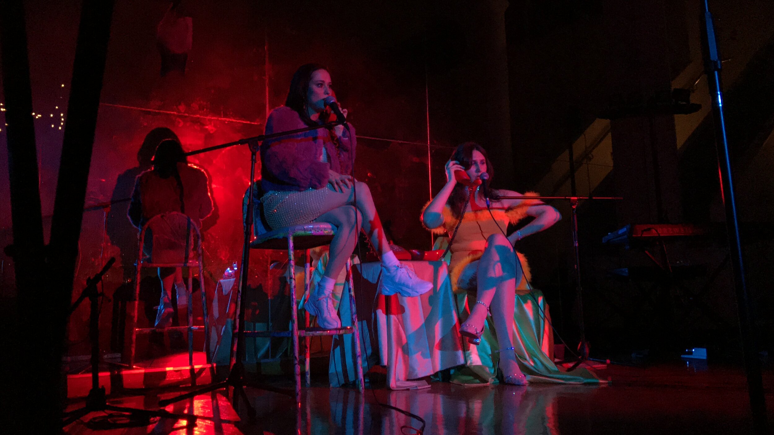
An example of theatrical lighting designed by Emerson Kafarowski
Theater production staff work under extreme time pressure as venues seek to minimize downtime between shows. With a typical show containing hundreds of unique lighting scenes, the lighting designer must work quickly to set up, tweak, and program their designs during rehearsals. Their main tool during this time is the lighting console - a specialized interface allowing rapid command entry and control adjustment. Lighting consoles have buttons, sliders, and rotary encoders that are used for sequencing or adjusting lighting parameters.

A typical lighting console.
For all their benefits, lighting consoles are bulky and very expensive. Smaller or non-traditional venues may have a simpler or older console than the designer is familiar with, and some may not have a lighting console at all. In such cases, the designer must resort to using a mouse and keyboard. The extra keystrokes and time spent handling the mouse can impose a serious hit to productivity.
My sister Emerson is a professional lighting designer, and we wanted to work together to solve this problem. Our solution was to package the most important features from a standard lighting console into a customizable, portable and low-cost device that maintains compatibility with industry-standard software.
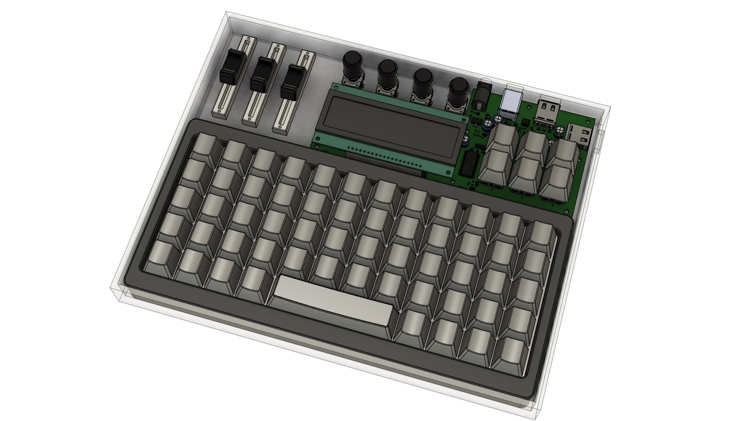
The EMRSNxEOS Concept, showing the Command Keyboard, the Moving Light Controller, and a set of encoders and sliders.
The Command Keyboard
Commercial lighting consoles have dozens of keys which perform different functions inside lighting control software. After developing muscle memory, the designer can enter commands quickly and efficiently. Without a lighting console, a designer must use the lighting software with their mouse and keyboard instead. Many of the commands require them to navigate through menus or enter multi-key combinations to achieve what could be accomplished with a single keystroke on a lighting console.
EMRSNxEOS features a custom mechanical keyboard, with keys mapped to software functions instead of regular QWERTY characters. The keyboard circuit is a off-the-shelf JJ40 ortholinear keyboard. The original keyboard firmware had limited ability to map buttons to key combinations, so we upgraded to QMK firmware . QMK features an easy-to-use web-based configurator, where the actions of each key can be assigned to arbitrary letters, numbers or key combinations. Emerson customized it for her particular use case but the configurator makes it easy for any lighting designer to customize which key combinations they want and where on the keyboard they should be located.
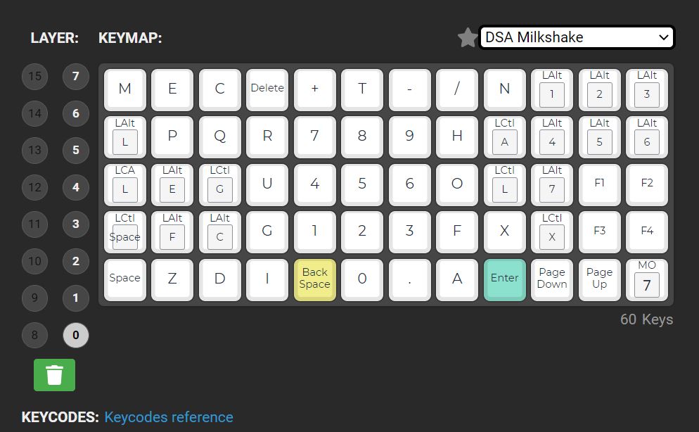
The final keymap in the QMK configurator. EOS users may recognize some hotkeys!
The keys have custom backlit text that describes their function. Clear, blank keycaps were painted in matte black or grey. A laser marker was used to remove the black or grey paint layers, exposing the clear keycap in the shape of the text. Cool white LEDs (6000K) shine through the clear keycap, illuminating the markings and making the keys easily visible in both lit and dark environments.
A laser marker removes the painted layers, revealing the clear keycap underneath. Additional passes etch further into the clear keycap, creating a clean matte white appearance.
The Moving Light Controller
The Moving Light Controller (MLC) works in conjunction with the Command Keyboard and allows the designer to intuitively adjust analog lighting parameters without needing to manually type in numbers or use a mouse.
The Moving Light Controller. Various light fixture adjustments can be selected with the six keys, and adjusted using the encoders.
At the core of the MLC is an ESP32 microcontroller, which connects to a computer running the ETC EOS lighting software. Using a virtual COM port, it communicates with the software using the Open Sound Control (OSC) protocol. EOS software regularly broadcasts information, such as show status, command information, and parameters about the active lighting fixture or device. The MLC parses and processes the information and presents the designer with information similar to that found on commercial lighting consoles. This information is shown on an OLED display. The OLED has excellent contrast and doesn’t require a backlight, both necessities for reducing distraction and glare when operating in a dark theater tech room.
The interface allows the designer to operate various analog controls using four rotary encoders. The controls are generally grouped by categories, such as intensity, color, focus, and position among others. The controls are accessed by category through the 6-button selector, and if more than four controls are present in a category, pages of controls can be advanced by tapping the category button multiple times. Turning the encoders will adjust the analog values of the control. By clicking the button of the encoder, the control changes between coarse (fast) and fine (slow) adjustment, allowing for both large and small changes.
The MLC also has an integrated USB hub controller, which provides all-in-one computer connectivity for everything a designer would need in the field - the MLC, the Command Keyboard, a USB-to-DMX bridge for connecting to the lighting system, and an authorization key for the EOS software.
Finally, the ability of the ESP32 to create a Wi-Fi access point is handy for networking multiple devices (in an offline way) in venues without Wi-Fi. For example, if the designer needs leave the tech room to inspect the lighting from a different angle, they can connect their computer and their phone to the MLC’s hotspot, and use EOS’s phone app to control the system.
Development
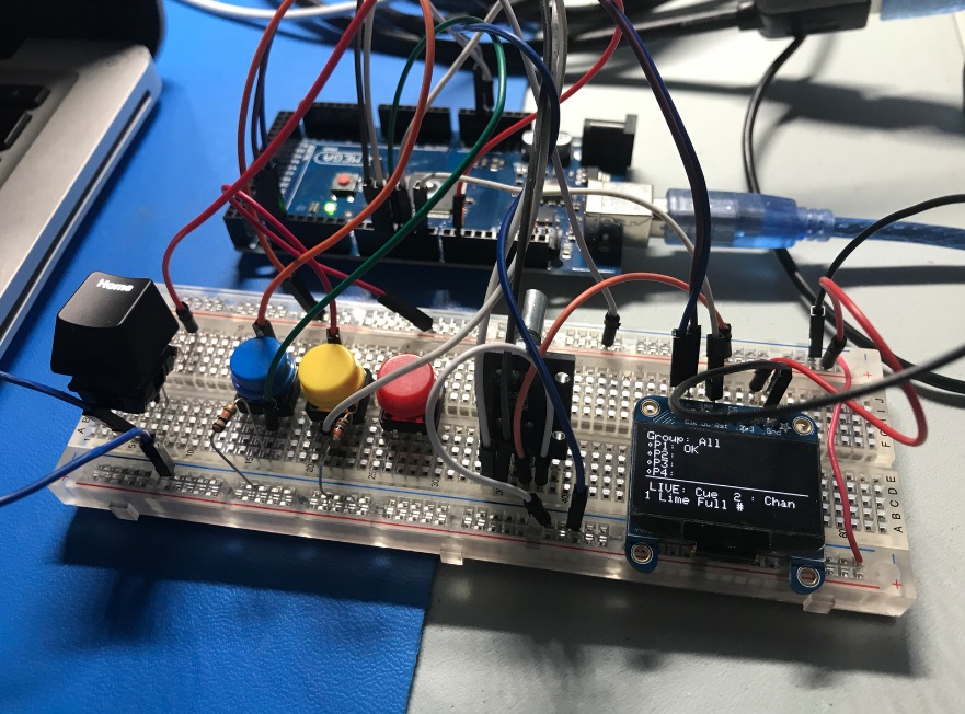
ETC, creators of the popular theater lighting software EOS launched an initiative called #Lighthack, an educational kit that encouraged creatives and makers to design their own lighting control interfaces using the OSC protocol. The sample project could control and display some preset parameters of a light using an alphanumeric LCD, a few buttons and some rotary encoders. The Lighthack code served as a launching point for a custom breadboard project with a few buttons and an encoder, running on an Arduino Mega.
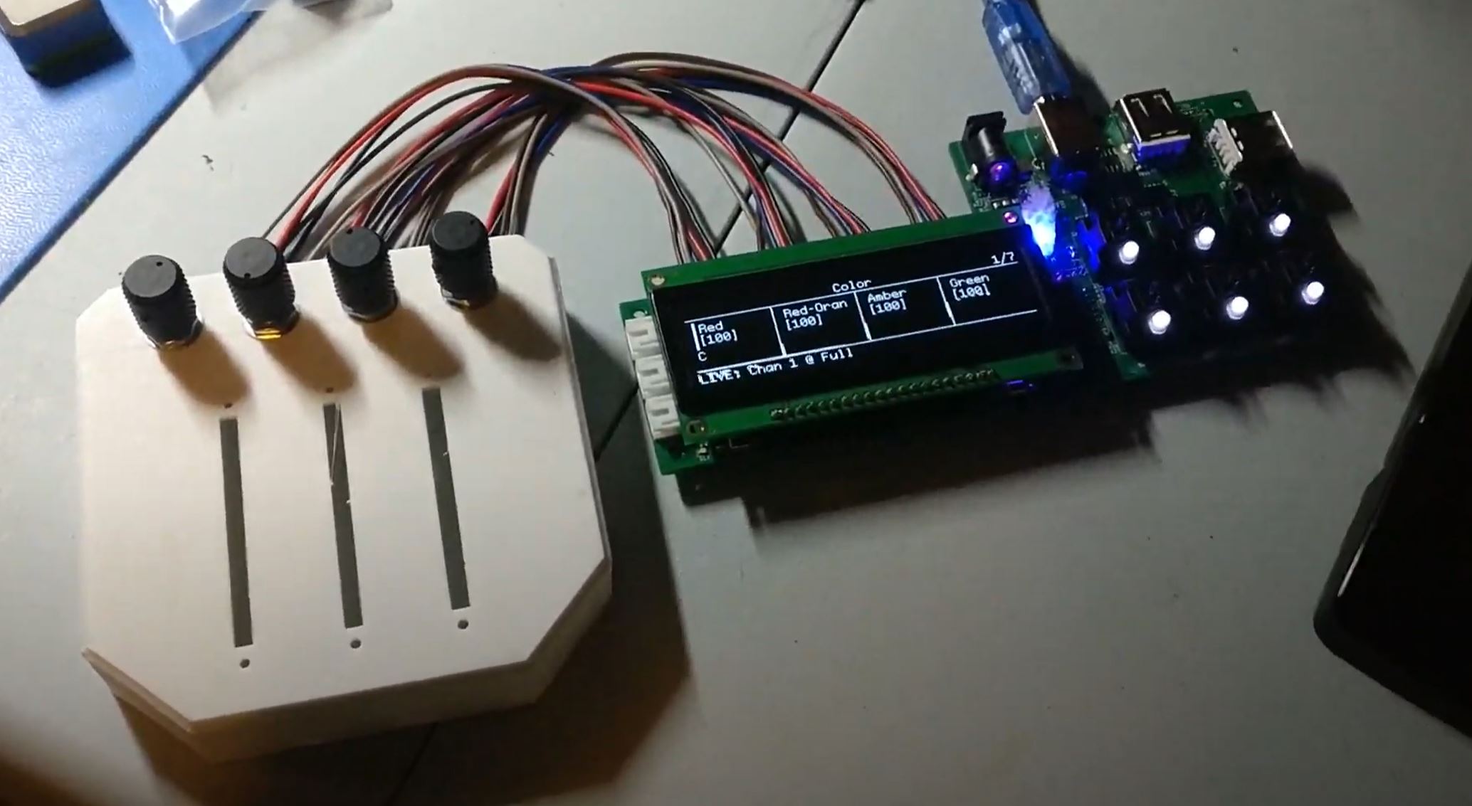
Proof of concept, where the encoder and buttons could adjust some lighting controls and display information on the OLED
After building a proof of concept, we wanted to add a better screen and the ability to control any parameter of the selected stage light rather than a preset or hard-coded parameter. At this point, we upgraded to the ESP32, which had better performance and more storage for the graphics library, more RAM for buffering OSC commands, and Wi-Fi capabilities.
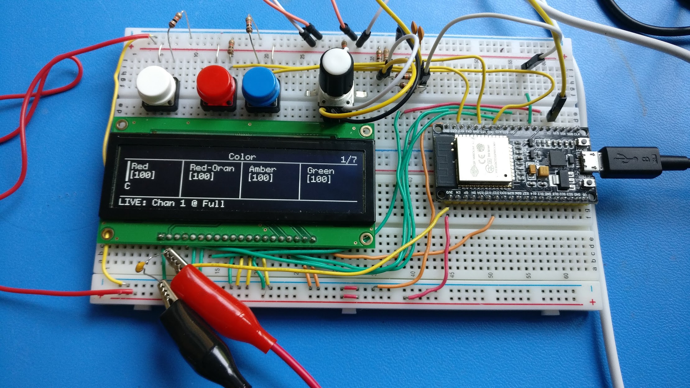
The project outgrew the capabilities of the Mega, and the project was ported to the ESP32. Because the ESP32 supports the Arduino framework, this was quick and easy.
The first PCB revision brought the idea into reality, both in an inspirational way and in a ’tear your hair out frustrating’ way. Through testing, I uncovered a number of circuit and footprint errors, which required (sometimes extensive) circuit surgery. In this revision I also discovered that for our application, driving the display with serial, rather than parallel data was sufficient, which freed up a lot of pins. I also discovered that using a second microcontroller (the ATMega328P to the left of the ESP32) to sample and report the encoder positions added a lot of complexity to the design.
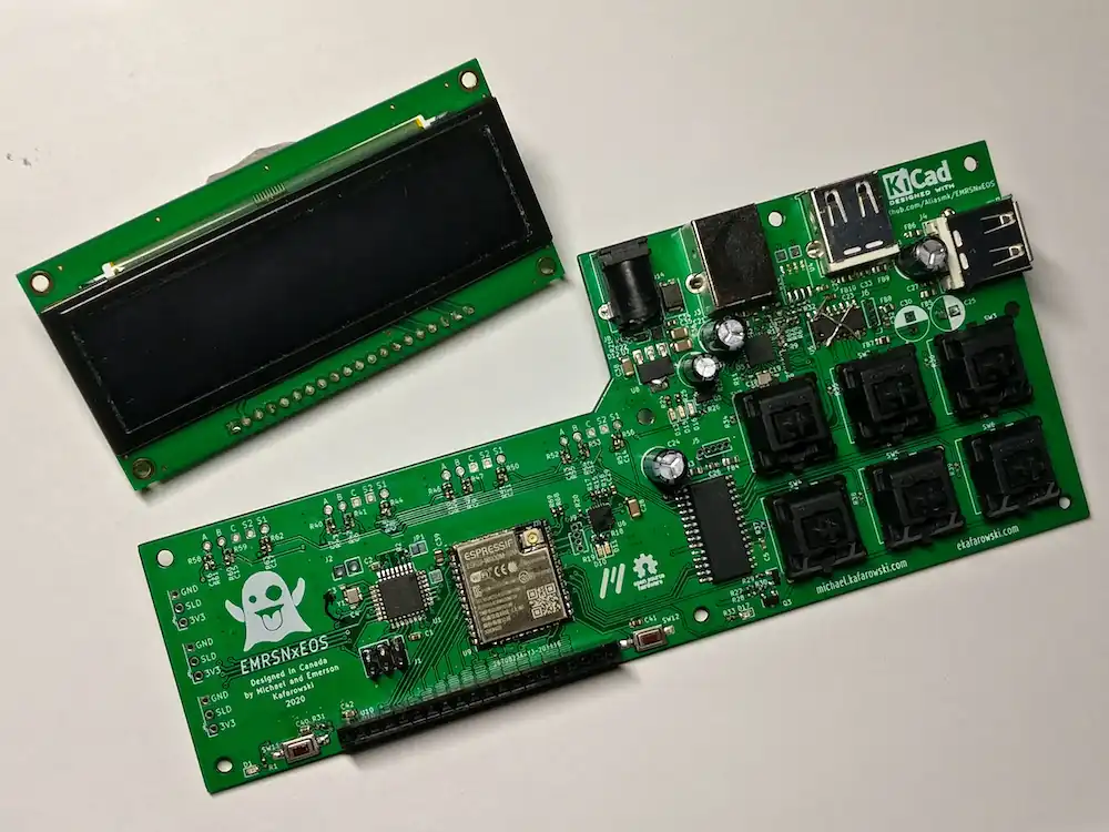
The assembled V1 PCB, sans keycaps.
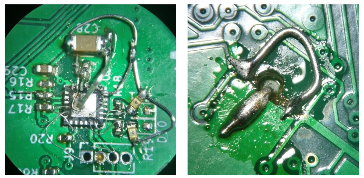
Two of the ‘finest’ examples of circuit surgery on the V1 board. Left: the USB-to-Serial bridge IC has two different packages. I accidentally used the schematic symbol for the smaller package and the PCB footprint for the larger, so I had to completely reconnect all the pads with fly wires. Right: the USB hub controller’s only ground was the center pad. I hadn’t connected the pad to a net, so I had to drill through the PCB and solder a wire through the hole and onto a ground plane.
I learned a lot from the circuit of the first revision that I applied and corrected in the second revision. The second revision worked great and had a few improvements, such as headers for easier connection and disconnection of the encoders and sliders. With more free pins, I could eliminate the ATMega and directly connect all the rotary encoders to the ESP32.
Final Results and Next Steps
We finished 80% of the project in time for the DME Creators Grant showcase, with only the fader wing (sliders) and the enclosure design still outstanding. Emerson created the demo video below, which highlights the main features of the console as well as brief notes about its development.
We wish to share the project with the lighting design community to serve as inspiration and a platform to build on. At present, all code and design files are open source and freely available on Github. We plan to complete the enclosure and fader wing, and then offer a kit or fully assembled version for sale for anyone that wants to use it but doesn’t want to put it together themselves. More details about the kits coming soon.