LED Strip PWM Controller
(2016) | 725 words (3 mins)
My father recently bought a Philips 12V white LED strip. Unfortunately, it was too bright out of the box, so I designed a PWM (Pulse Width Modulation) controller to allow him to dim it to the desired brightness efficiently. This was the first project I had designed a PCB for, so it was a great learning experience.
Requirements
The criteria for this project was to dim the LED strip while being powered by a 12 volt power supply. The PWM circuit was chosen for its simplicity, efficiency and practicality. An inline resistor would not be suitable as it would drop voltage across it and would dissipate too much heat. A buck converter would not dissipate as much heat, but pure open-loop voltage control of LED brightness is undesirable because forward voltage is sensitive to many factors such as temperature, which could result in inconsistent brightness over time.
PWM and Circuit Background
PWM works by rapidly switching on and off a voltage source in a square wave pattern. With smaller duty cycles, the average voltage over a period is decreased and the light dims, while the peak voltage level is maintained. This is important for devices such as LEDs which require a certain minimum voltage to turn on.
The completed schematic in Eagle CAD
The dimmer consists of a square wave oscillator and a switch to drive the LED strip. The oscillator is built with a 555 timer configured as an astable multivibrator with different RC time constants connected to the discharge, threshold and trigger pin. A capacitor, two diodes and a variable resistor are used to form the duty cycle configuration circuit. Turning the potentiometer knob adjusts the balance of the resistance and thereby changes the duty cycle of the square wave.
In order to drive the high current of the LED strip an IRF630 MOSFET is used by attaching the output of the 555 to the gate and wiring the LED strip in series between the 12V supply and the drain of the MOSFET.
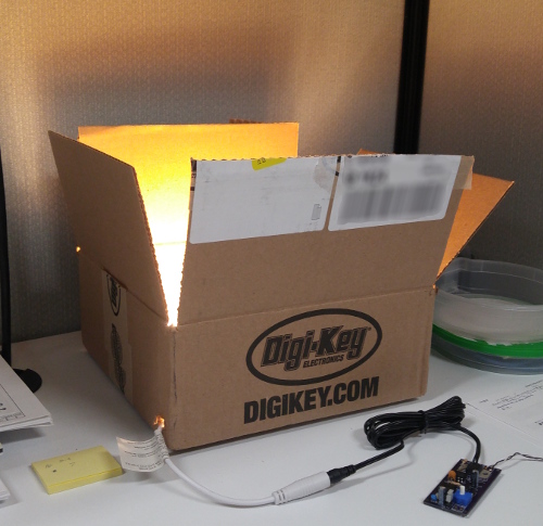
Next-day delivery for only $8 flat makes every Digikey.ca box that comes to my door a magical box.
PCB Design
As this controller was to be used beyond just an experimental phase, a more permanent component mounting solution was required. I decided to try my hand at designing a PCB because I wanted the final product to look and perform professionally, and because I didn’t want to use perfboard. With the assistance of Sparkfun Eagle Tutorials I designed my first PCB. Some considerations that went into the design included ensuring that high current carrying components centered around the MOSFET were as close as possible to each other and that traces between them were sufficiently large enough to not pose a safety hazard in the presence of high current. I also spent considerable time tidying up the auto-router traces and removing unnecessary vias. It took multiple revisions until I was happy with the board, but then I shipped it off to OSH Park for fabrication.
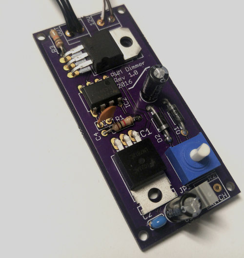
Purple PCB from OSHPark
A week later I got my three boards back and I was super happy with how good they looked. I really like OSH Park’s quality of work and I think the purple solder mask looks really nice. It was my fault for not catching this before accepting the order, but for some reason the silkscreen layer with my component values didn’t make it on to either side of the board. In addition, I misjudged the size of a resistor and a capacitor footprint, and ended up having to get creative with the leads to get them to fit. However apart from those issues, the board worked like a charm.
Testing and Final Notes
I performed 3 days of 8 hour endurance tests on the board at full brightness. The MOSFET barely got warmer than the individual LEDs on the strip, even without any heatsinking apart from the copper pour on the PCB.
I also formed a better understanding of the 555 timer - this circuit is much more elegant than the 555 circuit I used in my No uC EEPROM Reader that needed a 5M ohm resistor!
There is still much more that can be improved with this project - with SMD components it could potentially be made much smaller. It could also do with a (perhaps 3D printed) housing as well.